Function
The NIC Configuration page allows you to configure an internal switch module port for connecting to a NIC.
Parameter settings of different types of switch modules vary according to options displayed on the WebUI.
Table 1 describes the buttons on the NIC Configuration page, and Table 2 describes the parameters on this page.
Button |
Description |
|---|---|
New Profile |
Sets Blade Slot, Profile Name, Associated Switch Profile (2X/3X), and Associated Switch Profile (1E/4E). The maximum number of NIC profiles is 128. |
Parameter |
Description |
|---|---|
Profile Name |
Identifies a profile. |
Node Type |
Indicates the type of a compute node where the NIC is located. |
MEZZ Card |
Indicates the NIC slot and type. |
Associated Switch Profile (2X/3X) |
Indicates a switch profile associated with slots 2X and 3X. |
Associated Switch Profile (1E/4E) |
Indicates a switch profile associated with slots 1E and 4E. |
Notes |
Provides additional information. This parameter is optional but cannot contain any Chinese characters. The value can contain a maximum of 47 characters. |
Associated Slot |
Indicates compute nodes associated with a configuration profile. You can click the slot number link to change them. For details, see Associated Slot. |
Operation |
Perform operations on a profile.
NOTE:
When you copy a profile, only the compute node type, remarks and NIC information are copied. NIC Teaming and vNIC configurations cannot be copied.
|


Parameter |
Description |
|---|---|
Slot |
Indicates the compute node slots associated with the vNIC. |
Status |
Indicates the compute node status. |
NIC Teaming Names |
Indicates the name of a NIC teaming. |
Work Mode |
Indicates the working mode of physical NIC ports. |
PVID |
Indicates the default VLAN of the connected switch module ports. |
Location |
Indicates the NIC location, which can be Mezz1, Mezz2, Mezz3, Mezz4, or LOM. |
Port |
Indicates the NIC port numbers which can be 0 and 1, or 0, 1, 2, and 3 based on the NIC type. |
PF Number |
Indicates the number of a physical function. |
PCIe Info |
Indicates PCIe information of a mezzanine card. PCIe information format: CPU bus number:device number.function number-NIC function number |
MAC Address/WWN |
A MAC address is displayed if the NIC port type is Ethernet. A WWN is displayed if the NIC port type is FCoE. |
Business VLAN ID |
Indicates the business VLANs associated with the vNIC. |
Uplink Ports |
Indicates the uplink ports of the business VLANs associated with the vNIC. |
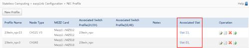
Associated Slot
- In the profile list, click a slot number in the Associated Slot column. See Figure 1.
 NOTE:
NOTE: If no slot is associated with a profile, the value of Associated Slot for this profile is None.
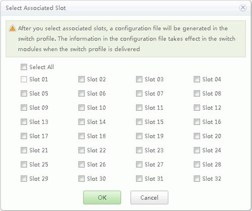
The Select Associated Slot dialog box is displayed, as shown in Figure 2.
- Select the slot number to be associated with the profile, and click OK.
The selected slot number is displayed in the Associated Slot column.
NOTE: The compute node in the selected slot and the compute node to which the policy imported must be of the same type.
Compute node slot description:
- When associated with a half-width compute node, the profile can be bound to slots 1 to 16.
- When associated with a full-width compute node installed in slots 1 to 8, the profile can be bound to slots 1 to 8.
- When associated with a full-width compute node installed in slots 9 to 16, the profile can be bound to slots 9 to 16.
- When associated with twin compute nodes, the profile can be bound to slots 1 to 16 or 17 to 32 based on the sub compute node slot number.
Creating a Profile
- On the NIC Configuration page, click New Profile.
The Import From Board dialog box is displayed.
- Set new profile parameters, see Table 4.
Table 4 Creating new Profile parameters description Parameter
Description
Blade Slot
Select the compute node slot from which NIC information is obtained.
Profile Name
The value of Profile Name contains a maximum of 20 characters, including letters, digits, and underscores (_), but cannot start with an underscore.
Associated Switch Profile (2X/3X) and Associated Switch Profile (1E/4E)
At least one parameter is selected.
Create a profile name in Switch Configuration. When no profile name is created, only NULL is displayed in a drop-down list box.
Notes
Provides additional information. This parameter is optional but cannot contain any Chinese characters. The value can contain a maximum of 47 characters.
- Click OK.
The profile configuration page is displayed. For Basic Info description, see Table 5.
Table 5 Basic Info description Parameter
Description
Profile Name
Indicates the name of a created profile.
Node Type
Indicates the type of a compute node where the NIC is located.
Associated Switch Profile (2X/3X)
Indicates a switch profile associated with slots 2X and 3X.
Associated Switch Profile (1E/4E)
Indicates a switch profile associated with slots 1E and 4E.
Notes
Provides additional information. This parameter is optional but cannot contain any Chinese characters. The value can contain a maximum of 47 characters.
NIC Location
Indicates the NIC location, which can be Mezz1, Mezz2, Mezz3, Mezz4, or LOM.
NIC Type
Indicates the NIC type such as MZ510.
Port
Indicates the NIC port numbers which can be 0 and 1, or 0, 1, 2, and 3 based on the NIC type.
Port Type
Indicates the NIC port type such as 10 GE.
Maximum Number of PFs
Indicates the PF number depending on the NIC configurations and types.
Switch Port
Indicates the switch port corresponding to the NIC port.
- The format of an Ethernet switch port is switch module slot number:compute node port number.
- An FC switch port is an FC switch module port connected to a compute node NIC.
PCIe Info
Indicates NIC PCIe information. PCIe Info format: indicates a PCIe root port (bus, device, or function)-NIC function number, such as 00:03.0-1 with 00:03.0 indicating the PCIe root, where, 00 indicates the PCIe bus number, 03 indicates the PCIe device number, 0 indicates the PCIe function number, and 1 indicates the NIC port number (PCIe function number).
Operation
Only the delete operation is allowed.
- Create a NIC team.
- Click Create NIC Teaming.
The Create NIC Teaming window is displayed.
- Set NIC teaming parameters, see Table 6.
Table 6 Create NIC Teaming Parameters Parameters
Description
NIC Teaming Name
The value contains a maximum of 20 characters, including letters, digits, and underscores (_), but cannot start with an underscore.
Select NIC
The NIC format is xxx:y, where xxx indicates the NIC position and y indicates the network port number.
The operation must meet the following requirements:
- The port types must be the same.
- The associated slots must be either slots 2X and 3X, or 1E and 4E.
- The number of detected NICs must be an even number.
- When the switch module uses the Ethernet switch plane, the slot corresponding to the selected NIC must be configured with a switch profile which is associated with a NIC profile. When the switch module uses an FC switch plane, FC configuration must be performed on the slot corresponding to the selected NIC.
Work Mode
The NIC supports Active-Backup, Balance, and LACP. The default mode is Active-Backup.
- Active-Backup: The NIC works in active/standby mode.
- Balance: works in load sharing mode.
- LACP: works in link aggregation mode.
- The LACP mode can be either of the following:
- Static LACP
- Dynamic LACP
- LACP Timeout: specifies the maximum time allowed for receiving packets.
- Slow: The timeout period is 3 seconds.
- Fast: The timeout period is 90 seconds.
Only the stack mode supports Balance and LACP.
For an Ethernet port, the NIC supports Active-Backup, Balance, and LACP. The default mode is Active-Backup.
- Active-Backup: The NIC works in active/standby mode.
- Balance: works in load sharing mode.
- LACP: works in link aggregation mode.
Only the stack mode supports Balance and LACP.
For an FC port, you do not need to configure the work mode.
NIC QinQ
Specifies the setting of the NIC QinQ.
Value:
- ON: Enable NIC QinQ.
- Off: Disable NIC QinQ.
Default value: Off
Only MZ520 and MZ522 support this parameter.
NOTE:If NIC QinQ is enabled, PVID cannot be set and the vNIC settings must meet the following requirements:
- Mode: When the work mode is Stack, this parameter can be Port or PF only. When the work mode is Twin, this parameter must be Port.
- vNIC Type: The value must be Ethernet.
- Business VLAN: The value must be domain vlan.
- VLAN Type: The value must be Domain Vlan.
After the NIC QinQ is enabled, the downlink ports associated with the domain VLAN can transparently transmit data through the VLAN, and the uplink ports provide the QinQ function.
PVID
The Port Default VLAN ID (PVID) can be set only for Ethernet ports.
This parameter is optional. The value is a positive integer from 2 to 4063 and must be in the range of the associated business VLANs.
If the switch module type is CX311, and Work Relation is Stack or Twin, the value of PVID cannot be the same as the VLAN ID of the FC SAN FCoE.
NOTE:If the associated business VLAN of the PVID is a domain VLAN, the valid PVID is the domain VLAN ID instead of the PVID of the NIC teaming.
Notes
Provides additional information. This parameter is optional but cannot contain any Chinese characters. The value can contain a maximum of 47 characters.
- Click OK.
The new NIC teaming is listed on the NIC teaming configuration page.
- Click Create NIC Teaming.
- Configure vNICs.
- Click Add vNIC Configuration.
The Add vNIC Configuration window is displayed.
- Set Add vNIC Configuration parameters, see Table 7.
Table 7 Add vNIC Configuration Parameters Parameters
Description
vNIC Name
The value contains a maximum of 20 characters, including letters, digits, and underscores (_), but cannot start with an underscore.
NIC Teaming Name
Indicates the name of NIC Teaming to which the vNIC belongs.
vNIC Type
Supports Ethernet, FCoE and FC, choosing either one based on the NIC.
FCoE configuration can be performed only when both the switch module and NIC supports FCoE.
Mode
Supports Port, PF, and VF:
- Port: indicates that the NIC is not virtualized. No other vNIC can be added after the configuration. Only Trans VLAN, Domain Vlan and Normal VLAN can be selected.
- If Normal VLAN is selected, the packets between compute nodes and switch modules do not contain Tags.
- PF: indicates that the NIC uses the PF function. The number of vNICs varies based on the PF number.
- VF: indicates that the NIC uses the VF function or that the NIC is virtualized on an OS. The number of vNICs supporting VF is 40 (vNIC*Number of NIC Teaming members ≤ 40). The vNIC supporting VF and vNICs supporting PF cannot coexist.
For an FC vNIC, the mode is always Port. For an FCoE NIC, the mode is always PF.
Business VLAN
If you select the Business VLAN associated with vNIC. Indicates the business types and uplink ports.
VLAN Type
Indicates the type of the associated VLANs.
VLAN ID
Indicates the IDs of the VLANs.
Notes
Provides additional information. This parameter is optional but cannot contain any Chinese characters. The value can contain a maximum of 47 characters.
- click OK.
The new vNIC is listed on the vNIC configuration page.
- Click Add vNIC Configuration.